If you have any further questions regarding the above discussed 2 4 ghz 10 channel remote control switch please express them in the comment section.
4 channel remote control switch circuit diagram.
If you press the same button on remote again it will turn off the output 1 at receiver.
Crystal based oscillator for reliability of operation.
Turn off the remote after use.
4 ch rf remote control is used to turn on off four different devices independently.
Circuit design of remote controlled light switch.
Pressing buttons 1 2 3 or 4 turns the corresponding output on pressing it again turns it off.
Supply transmitter.
Remote controlled switch this is the very simple circuit diagram of the ir remote control switch.
Emylo dc 12v 1channel remote control switch wireless rf relay wiring test instruction.
Remote controlled switch circuit diagram notes.
In this remote controlled switch circuit we are using tv remote to on off the ac light by pressing any button of remote and using the tsop1738 at receiver end.
Any of the four outputs can be configured to work independently in either toggle or momentary mode.
A single channel relay board is sufficient.
Receiver circuit is connected to ac appliance via relay so that we can control the light remotely.
The main components of the project are ic cd4017 and tsop 1738 ir receiver.
We use the normal switch in our daily life and after a long time used to these switching system we can no more interested in that.
5 vdc 200 ma.
Jumper selectable 8 bit.
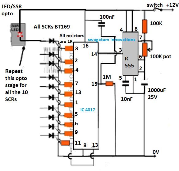
We have used ic 4017 to convert it into a push on push off switch.
It applies for all the buttons and 10 outputs.
A 4 channel relay module is used in this project in order to control the light.
This device is good for switching on and off up to 4 independent appliances by remote control.
Emylo dc 12v 1channel remote control switch wireless rf relay wiring test instruction.
433mhz universal wireless remote control switch ac 85 v 250 v 110 v 220 v 2 ch relay receiver module and rf 433 mhz remote controls from.
Alternatively the relay circuit can be built as per the circuit diagram.
3 to 5 vdc 5 v 20 ma receiver.
Before wiring the circuit make sure that the carrier frequency of the tv remote you have is 38 khz for that wire the sensor part only point your remote to the tsop1738 and press any switch if out put of tsop1738 goes low then ok your remote is of 38khz type nothing to worry almost all tv.
Simple 4 channel on off remote control introduction.
Outputs are buffered by bc549 npn transistors and can drive low voltage devices directly such us motors or be connected to either 5v or 12v relays to control.


