Some circuits would be illegal to operate in most countries and others are dangerous to construct and should not be attempted by the inexperienced.
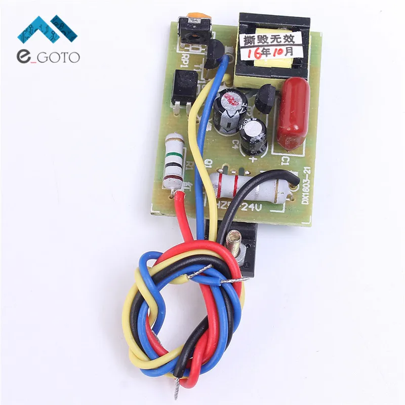
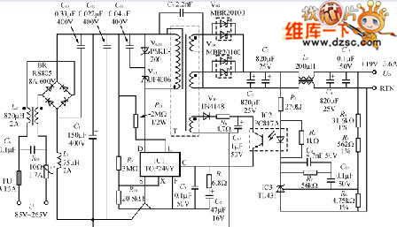
4 wires universal power supply module circuit diagram.
First power supply circuit is built with bd139 one zener diode and a few passive components.
The transformer voltage must be greater with 4v than dc stabilized voltage.
Diagnostic manual comes with.
Automatic light turn off page l 4 5.
Stop lights page l 3 4.
A wiring diagram is a streamlined standard pictorial depiction of an electric circuit.
Power windows page a 2 3.
The hot and neutral terminals on each fixture are spliced with a pigtail to the circuit wires which then continue on to the next light.
It shows the parts of the circuit as simplified forms and also the power and also signal links in between the devices.
You can usually get away with that but there s no reason to do it.
Headlights page l 1 2.
Power mirrors page a 3 4.
1992 1995 4 3l astro safari ignition system no start problem diagnostic manual.
Both transistor and voltage stabilizer must be mounted on a heatsink.
One 6a4 get shorted then i changed the supply bridge to armature and vice versa till one diode is shorted the motor is 1 5 hp rating 8amp.
This diagram illustrates wiring for one switch to control 2 or more lights.
Power supply and power control circuit diagrams circuit schematics note that all these links are external and we cannot provide support on the circuits or offer any guarantees to their accuracy.
C1 is calculated for 1a 1000uf so at 5a c1 must have 4700uf.
If you use an adapter then be sure to plug the 4 pin peripheral connectors into separate cables coming from the power supply.
Turnsignals hazard page l 2 3.
If you plug them both into the same power supply cable then you are drawing all the power of the pci express connector through a single 18 gauge wire.
Door locks page a.
Rear window defogger page a 1 2.
Universal power supply module 3wire about this video in this video i m telling about universal power supply module features specification connection ci.
In my design i used 220v dc by using 35 a bridge to power field supply of the motor i used 6a4 bridge to power armature supply but when i am connecting the said cct.
Daytime running lights page l 5 accessories systems 1.
The additional power transistor takes the load current of about 200ma.
Understanding diagrams page u 1 lighting systems 1.
Universal power supply circuit diagram.
The source is at sw1 and 2 wire cable runs from there to the fixtures.
Multiple light wiring diagram.
All of the information you need to diagnose a no start problem caused by the ignition module or the ignition coil or the distributor pickup coil.


