I used 12v high torque dc motor which i powered using there 3 7v li ion batteries connected in series which give around 12v.
555 pwm dc motor speed control circuit.
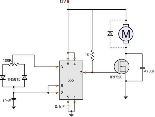
The heart of the circuit is a ne555 timer ic which is working as a astable multivibrator here.
The method of pwm is explained here.
Initially when the circuit is powered the trigger pin is in a logic low position since the capacitor c1 is not charged.
The word pwm is also known as pulse width modulation.
The above circuit diagram shows the speed controller using 555 with slight modification of our basic astable circuit.
Pwm dc motor control with ic 555.
This simple dc motor control or pwm circuit using 555 ic can be used to control the speed of a dc motor.
If duty cycle is more then the speed of the motor will be high if it is less the speed of the motor will be low.
For those who are not aware pwm or pulse width modulation is a modulation technique in where the width of the output pulse varies with with respect to time.
Here are the schematics of the dc motor speed control circuit.
This circuit uses similar pwm technique to control motor speed and uses ic 555 to generate pwm signals.
A simple dc motor controller circuit using ne555 is shown here.
The circuit is very simple and can be built in very short time if all parts are available with you.
I hope you enjoyed this tutorial and learned something new.
I will use this circuits to control my led strips in my car and the motor f.
So now using the potentiometer we are able to control the speed of the dc motor or the pwm signal produces by the 555 timer ic.
The design of a simple motor speed controller using pwm may be understood as follows.
Suppose there is a voltage of 5 volts which is turning on and off in an interval.
This on off signal is mainly presented as duty cycles now if there is 50 duty cycle in the output voltage will be 50 of 5 volts so.
555 very simple pwm to dim led dim dc lights and control the speed of dc motors.
Many dc motor speed control circuits have been published here but this is the first one using ne555 timer ic.
A pwm circuit based on timer ne555 is the heart of this circuit.
The above conditions initiates the oscillation cycle making the output change to a logic high.
Depending upon the duty cycle the speed of the motor will vary.

